Description
EMG ELHY Thrusters
Download EB Thruster User Manual
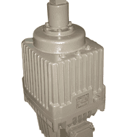
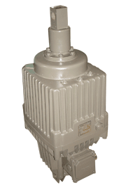
The electrohydraulic thrustor (Elhy) comprises all basic components of an hydraulic system in one single packaged unit. It consists of an hydraulic pump with electric drive motor, a closed hydraulic guide system and the working cylinder with piston and lifting rod and converts electric energy by way of hydraulics into mechanical straightline movements.
The Elhy devices are available in three different series of uniform functional principle, internal setup, and outer appearance. Since the only difference between the series are the mounting dimensions, the data given in this catalogue apply to all three series.
The motor casing houses the stator of the drive motor which is designed as a threephase asynchronous squirrel-cage motor. The electric connection is via the terminal box which seals the motor casing tightly. The feet cast en bloc with the motor casing serve to mount the Elhy device. On the one hand, the rotor with shaft is supported in the motor casing, on the other hand in the end shield. The blade wheel of the pump is mounted on the shaft. The guide cylinder with piston which moves axially is situated above the blade wheel. The device is filled with hydraulic fluid up to the level of the inlet opening. In the version which is equipped with pullback springs, the latter are accommodated between the piston and the bottom of the guide cylinder.
The adjusting spring (standard series) or attenuation spring (series in compliance with DIN 15430 including special versions following DIN 15430) is mounted on the lifting rod of the Elhy device. The connecting bolts of the adjusting spring, e.g. for connecting the brake linkage, are located at the same level as the bore in the lifting rod so that height of installation h1 is obtained in line with the basic design. The connecting butt strap of the attenuation spring has the same dimensions as the pertinent lifting rod head so that the assembly dimensions are identical for devices with and without attenuation spring.
Elhy devices can be equipped with inductive or mechanical switching elements thus allowing supervision of release and/or closing positions of the brake as wel I as any wear of brake linings.
EMG ELHY EB 12/50 |
EMG ELHY EB 20/50 |
EMG ELHY EB 50/50 |
EMG ELHY EB 50/100 |
EMG ELHY EB 80/60 |
EMG ELHY EB 80/160 |
EMG ELHY EB 125/60 |
EMG ELHY EB 125/160 |
EMG ELHY EB 150/60 |
EMG ELHY EB 150/160 |
EMG ELHY EB 250/60 |
EMG ELHY EB 250/160 |
EMG ELHY EB 320/100 |
EMG ELHY EB 630/120 |
EMG ELHY EB 120-40 |
EMG ELHY EB 220-50 |
EMG ELHY EB 300-50 |
EMG ELHY EB 500-60 |
EMG ELHY EB 500-120 |
EMG ELHY EB 800-60 |
EMG ELHY EB 800-120 |
EMG ELHY EB 1250-60 |
EMG ELHY EB 1250-120 |
EMG ELHY EB 2000-60 |
EMG ELHY EB 2000-120 |
EMG ELHY EB 3000-60 |
EMG ELHY EB 3000-120 |
EMG ELHY EB 6300-120 |
EMG ELHY EB 320-50 |
EMG ELHY EB 320-100 |
EMG ELHY EB 500-50 |
EMG ELHY EB 500-100 |
EMG ELHY EB 800-160 |
EMG ELHY EB 1250-160 |
EMG ELHY EB 1500-60 |
EMG ELHY EB 1500-160 |
EMG ELHY EB 2500-60 |
EMG ELHY EB 2500-160 |
EMG ELHY EB 3200-100 |